Controlling distance between two points
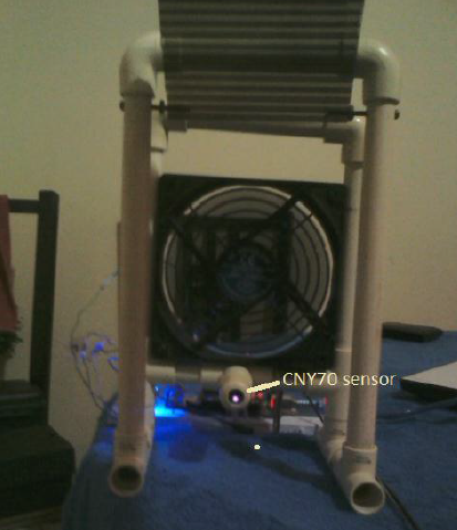
This project consist in create an automatic control for the motion of an object A in relation with an object B . The object A is a plastic piece and object B is a CNY70 proximity sensor, the sensor is fixed, the movement of the plastic piece is induced by a DC fan.
The project objective is to set the plastic piece at a distance X, this value is entered in the computer via an interface created in LabView, this distance should not vary if the structure moves, the fan speed is automatically adjusted so that the distance X is always the same.

The tools available to me
CNY70 Sensor
The CNY70 is a short range infrared sensor based on a light emitter and a receiver, both pointing in the same direction and whose operation is based on the reflectivity of the object and the reflected ray detection by the receiver.

Arduino Card (Data acquisition)
In this project the Arduino is used as an interface between the computer, and input and output signals, The A0 pin is used to read the analog signal CNY70 sent by the sensor and the A1 pin to send analog signal to the fan.

Analog Signal acquisition
As already mentioned CNY70 reflective optical sensor is used to measure the distance between point A and point B. The sensor is supplied with a voltage of 5 V in the terminals 1 and 4 as shown in the diagram The pin 2, the cathode of the infrared LED is connected to a 330 ohms resistance and to ground. The Pin 3, the emitter of phototransistor is the output signal. The Arduino reads this signal
between 0 and 5 V, and it is interpreted as a distance.

To adjust the analog sensor signal that is sent to the Arduino card, a potentiometer was used and it was calibrated to send the signal as high as possible when the fan is at maximum power.
Reading the analog signal from the card
The code used is as follows:
Arduino
int dato0 =0;
int wep=0;
void setup()
{
Serial.begin (9600);
}
void loop()
{
dato0 = analogRead(0);
wep = dato0;
Serial.println (wep);
delay (100);
}
Labview code:

Signal interpretation by LabVIEW
LabVIEW can read information by serial protocol thanks to the NI VISA library. The information is sent by a USB cable and use the serial protocol; An arrangement was made in the program because the sensor sends a weaker tension as far is the body B, and wanted to get the opposite behavior, to obtain a higher voltage when the distance between the sensor and the object is bigger. This was achieved by multiplying the signal by -1 then adding 700 units, to set to 0 when the object is at rest, it was finally divided between 139.2, thus when the object is at rest reading the signal displays 0 volts and 5 Volts when the fan is at maximum power.

Sending the analog signal from LabVIEW to Arduino.
The motor control is done by Labview; LabVIEW sends a digital signal
through the serial port to the Arduino board. The Arduino board has a range from zero
up to 254 bits in serial port, with 0 bits being equivalent to 0 V. and 254 bits to 5 volts.
A range between 0 and 5 to display in the graph was established, with 0 being the fan off and 5
maximum power. In below graph the voltage was changed manually by a numerical control in Labview

The arrangement that was made in the code was 254 (the maximum value in the range of 5 Card v) divided by 5, giving it 50.8 to vary the power output from 0 to maximum power.
It should be mentioned that you can only use integer variables for the serial protocol for the Arduino board, we can not send dual rate values for example 4.4 or 3.7. To solve this we use the range card that goes from 0-254 in its serial protocol, so if we want to send a signal of 4.4 volts, multiply 4.4 by 50.8, which results in 223.52, as we can not send decimals, we convert this value to an integer variable and a value of 224 interpret what the card is sent as 4.4 volts

It should be mentioned that you can only use integer variables for the serial protocol for the Arduino board, we can not send dual rate values for example 4.4 or 3.7. To solve this we use the range card that goes from 0-254 in its serial protocol, so if we want to send a signal of 4.4 volts, multiply 4.4 by 50.8, which results in 223.52, as we can not send decimals, we convert this value to an integer variable and a value of 224 interpret what the card is sent as 4.4 volts

Sending the signal from the Arduino board to the engine.
The Arduino board receives the digital signal via the serial protocol, converts it to an analog signal and sends it to the motor by the pin 3.
Here is the source code used by the Arduino board.
const int motor= 3; // *********** Sets variable motor to analog output 3
int speed; // ********** ********Variable for the motor speed
void setup () {
Serial.begin (9600); // ********** Speed for serial protol 9600 bauds
pinMode(motor, OUTPUT); // *** The variable motor is going to output the signal
}
void loop () {
speed = Serial.read(); // ********* Speed variable recieves signal from labview,
analogWrite(motor, speed); //***** Output speed value to the motor
delay(100);
}
This is the graph of the signal sent by the Arduino board to the motor 3 v.

Power Stage
The fan used was a direct current motor 12 v. The Arduino board can only supply 5 V maximum, so it was necessary to create a power stage for this, a TIP 122 transistor . The analog signal sent from the Arduino board is introduced directly into the base of the transistor, the collector is connected to the negative side of the fan. The emitter to the Arduino ground and 12 V source making a common ground. With this configuration when the card sends 5 V transistor passes 12 V in the source.

As shown in the graph, to send a signal of 5 volts, transistor let pass all power supplied by source 12 V and the engine will work at maximum power.

General Operation
- The sensor sends a beam of light through the infrared LED, it bounces against the object plastic and is detected by the phototransistor, which interprets it as an analog signal, the farther the object, the smaller the signal.
- The Arduino board receives the signal sent by the sensor in analog input A0, the analog signal is converted into a digital value, stored in a variable of type integer, and its sent to to the computer by serial protocol.
. - Labview receives the value of the variable, and read every 100 milliseconds thanks to a while loop, as the signal is weaker if the subject is further away from the sensor, an arrangement was madewithin the LabVIEW program, to show in the graph a value of 0 if the plastic piece is at rest and a value of 5 if the fan is at its maximum power.
- Labview compares the value of the actual distance to the desired distance, and makes a subtraction between both distances, this is known as an error, in the PID control, LabVIEW calculates how much must send the engine power to reduce the error to 0
- Labview signal is sent by the serial protocol to the Arduino board.
- The Arduino card converts the digital signal received by the by the Arduino protocol, converts into an analog signal, and sends it to the circuit via pin 3
- The signal reaches the base of the transistor and depending on its intensity, certain current passessource 12 volts, and is sent to the fan..
No hay comentarios:
Publicar un comentario